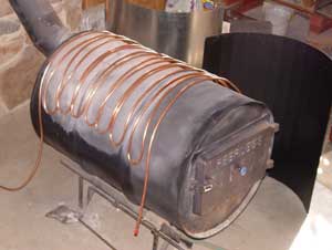
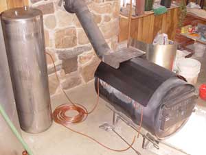
25 January: The heat for our water system will come from solar collectors, to be installed later, and a heat exchanger on the wood stove. About 40 feet of copper tubing is wound back and forth over the stove and then covered with a heavy steel plate to contain some heat. A small pump will push water through the coils. Most of the stove’s output will continue to heat the house by convection, as it always has, but we have also installed a fan in the heat register to improve circulation. The stainless-steel tank in the right photo is for our domestic hot water supply. All photos by John Sweet unless otherwise credited.


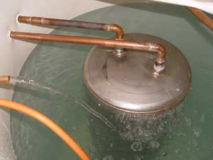
Ken Schaal watching the tank fill with water, left, and setting up the pumps. The green hose is supplying water to the tank, the tube penetrating the far side of the tank will draw water for the heat exchanger, and the two orange tubes in midair are the supply and return for the floor. One of these pumps serves the heat exchanger, the other goes to the floor, and a third will serve the solar collectors later on.


26 January: Ken is putting the domestic hot water tank into the large tank and filling it with water. The large tank is filled about two-thirds and we are adding enough water to the smaller one to cause it to sink. The new fan in the heat register above the stove can just be seen in the upper right corner of the left photo.
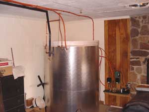
31 January: The plumbing is complete and we are now filling the large tank to a level just below where the pipes penetrate the liner. The orange pipes go to and from the radiant floor. The small, green box on the wall at right is a controller that works with a thermostat in the bathroom to turn the floor pump on as needed. The copper pipe at left in the right photo feeds the stainless-steel tank while the one at right is used only when the level in the large tank needs to be topped up. The black, insulated pipe in between is our domestic hot water, which now feeds into our old electric water heater and from there is piped to kitchen and bathrooms. The electric heater now serves only to top up the temperature if the solar/wood heat should fall too low. We expect that it will come on very little.
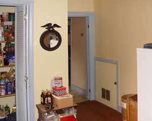
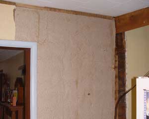
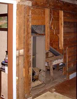
10 March: After a brief respite from any sort of house project, we are finally starting on the kitchen. The left photo was taken from the middle of the old laundry room. The pantry is at left and the doorway into the kitchen is at center. The small door leads to a storage space under the stairs and also to an old oil-burning furnace, which we consider a fire hazard so it is unused. That whole section of wall is coming down so we can remove the furnace and put a new pantry in its place. 11 March: Now we are in the kitchen looking at the same wall. The door frame is gone along with the first two layers of wall covering. The wall here had wallpaper over paneling, under which was at least six more layers of wallpaper, then cardboard, and finally 1" x 6" oak boards.
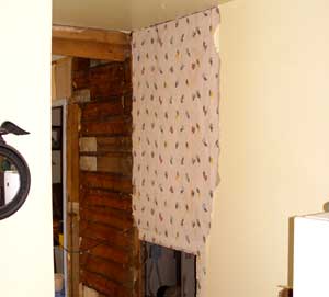
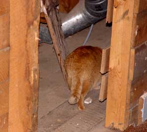
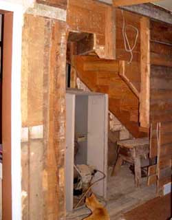
Looking from the old laundry room again, we see the oak boards in the kitchen and more wallpaper exposed. On this side there was yellow-painted drywall covering no less than eight layers of wallpaper. Rudy goes exploring at every opportunity. He has loved all of the new areas we have opened up. Here he is looking under the stairs.
13 March: Looking from the kitchen, the old furnace is somewhat exposed. The space around it is well packed with ductwork. 14 March: More wall is down and the ductwork is gone, as Rudy inspects the job.
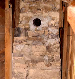
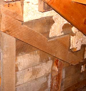
18 March: With the old furnace gone, the chimney is exposed. We are looking straight into the space that will become our new pantry. Also exposed are some artifacts from earlier remodeling. The right photo shows the remains of an old stair stringer with the new one above and remnants of wallpaper in between. We believe that the stairs were raised to make room for the furnace when it was installed. There is also evidence that the living room wall had been taken down in order to move the furnace into that space.

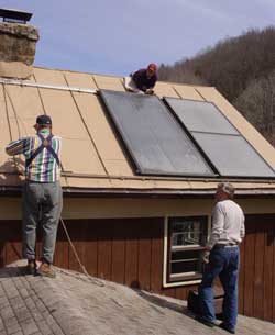
21 March: The big day! We are finally getting the solar collectors mounted. Shane Wiseman and Art Applegate lift a panel off the fork lift, left. Then, with Ken Schaal, we fit the second panel in place on aluminum rails bolted to the roof.
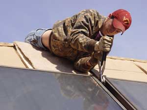
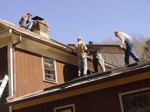
Shane tightens the connection between two panels, then we all lift another one up and push it into place. Right photo above and left photo below by Char Sweet.

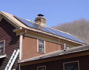
The left-most collector fit quite tightly between the rails and had to be pushed rather hard but finally all six are in place. We put in place all of the pipe that connects the collectors to the pump and storage tank in the basement, as well as the sensor that tells the pump when the collectors are warm enough to operate.

25 March: The new pantry is under the stairs and one of the steps had to be realigned in order to create headroom below. We essentially lifted part of a step up and rebuilt the riser. The old step partially blocked the pantry door. A duct from the old furnace came up through the step, which remains unpatched.


5 April: We have decommissioned the kitchen so the dining table and icebox are now in the living room. Cooking is done in the cabin and we eat supper there. We still have a microwave and some utensils in the house so we can have breakfast and lunch here. Once work is fully up to speed we will seal off the opening from the living room into the kitchen to control dust.
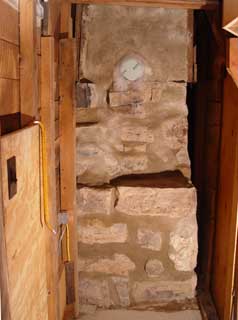

6 April: The old stone chimney will form the back wall of the new pantry. The mortar had no structural integrity so we reworked it with modern mortar. A sealer will be applied later. 10 April: Back on the outside, we have encased the piping for the solar collectors in aluminum downspout, partially for protection and partially for aesthetics. The pipes come from the storage tank in the basement, lower left, up through the lower roof, then out and around the gutter to reach the collectors on the upper roof.


19 April: The pumps and controllers for the heating system are finally complete. The storage tank is to the left, out of the photo. The wood stove with heat exchanger is at right. The leftmost pump serves the collectors and is controlled by the unit highest on the wall in the left photo. This controller has three sensors that read the temperature in the collectors and at the top and bottom of the tank. When the collectors reach a preset amount hotter than the water in the bottom of the tank the pump starts. When the collectors cool and/or the water heats up such that there is only a small temperature difference, the pump stops and the water drains back to the tank. The middle pump serves the radiant heat in the floor. The pump at right serves the heat exchanger. A controller activates this pump only when the stove is hot. The white box on the floor is an uninterruptible power supply, which keeps things running during a power outage.
With our “solar system” up and running it seems like a good place to go to a new page. The story continues as major deconstruction gets under way.